If the 'B' status LED flashes on a BCDC Alpha charger (25A, 50A, or 50R) with the control button solid, it signals a hard fault.
This means charging has stopped, usually due to poor power or ground connections.
This article explains how to check and clean connections and perform a power cycle reset.
REDARC recommends seeking the support of a qualified auto electrician or technician.
Important
In this article we explain the need for testing to determine the cause of the issue. Testing may involve changes to the installation or wiring. For your safety and accuracy, REDARC recommends engaging a REDNetwork member or a suitably qualified auto electrician - Find Your Local Installer
This information is applicable to the following BCDC Alpha chargers:
- BCDC Alpha 25A DC Battery Charger (BCDC12025B)
- BCDC Alpha 50A DC Battery Charger (BCDC12050B)
- BCDC Alpha50 R DC Battery Charger (BCDC12050R)
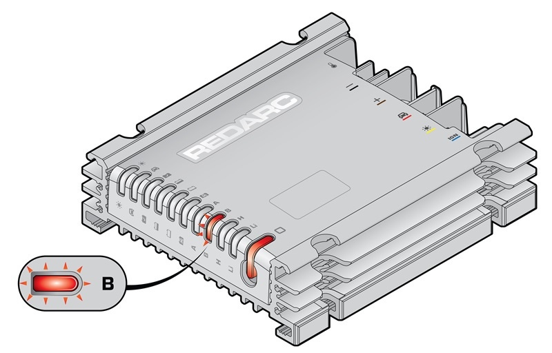
What does this look like?
The BCDC Alpha B status LED will flash along with a solidly illuminated control button LED, this is considered a hard fault condition.
What does the flashing 'B' LED mean?
This fault indicates that the BCDC Alpha has detected a possible internal hardware fault.
Will the BCDC Alpha still charge my battery in this condition?
In this fault condition, being a hard fault, the BCDC Alpha will cease charging.
A Hard Fault means the system will stop charging. A Hard Fault is indicated when the LED corresponding to the fault condition flashes red and the Control Button LED illuminates solid red.
What can cause this fault mode?
The BCDC Alpha has detected abnormal operation or an internal hardware fault.
How to determine the cause of the fault?
Below is a list of the common causes and repairs.
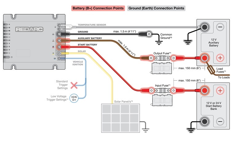
A) LOOSE CONNECTION AT THE START BATTERY TERMINAL / FUSE HOLDER OR LOOSE GROUND CONNECTION AT THE BCDC
The most likely cause of the internal hardware fault is a poor power supply caused by a loose or poor ground circuit.
Things to check:
- Ensure connection points are clean, not damaged, or loose.
- Remove battery terminal and ensure a clean surface area is provided for the terminal.
- Inspect the ground wire (-) to ensure it has a suitable ground connection, such as a terminal attached to bare metal (unpainted surface).
- Ensure each crimp connection is strong, a small tug on each wire can confirm this.
- Once all connection points have been addressed, refer to step B.
B) CARRY OUT POWER CYCLE PROCEDURE
Once the power supply and wiring connections have been checked and/or repaired, it's advisable to carry out a full power cycle to reset the BCDC Alpha. This is achieved by following the disconnect and reconnect procedure listed below.
Disconnect procedure:
- Start battery fuse
- Auxiliary battery fuse
- Solar
- Start battery
- Auxiliary battery
- Ground
- Vehicle ignition
- Battery temperature sensor
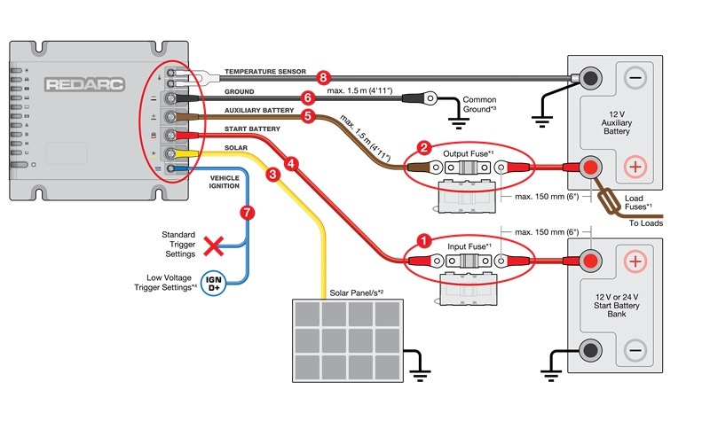
After being disconnected for 5 minutes, reconnect the BCDC in the following order.
Reconnect procedure
- Battery Temperature Sensor
- Vehicle Ignition
- Ground
- Auxiliary battery
- Start battery
- Solar
- Auxiliary battery fuse
- Start battery fuse
- Re-check operation
If the problem persists, contact REDARC Technical Support.
