If a BCDC shows a flashing profile light and isn’t charging, it is in standby mode due to an issue with the vehicle input (red) wire. The unit won’t charge from the vehicle but will still charge from solar if available.
Common causes include undersized cables, loose or poor connections, and faulty fuse protection, all of which can cause voltage drop.
Troubleshooting involves checking and replacing fuse protection (MIDI fuses recommended), cleaning and tightening battery and ground connections, and ensuring strong, reliable wiring.
REDARC recommends seeking the support of a qualified auto electrician or technician.
Important
For your safety, REDARC recommends installation by a qualified auto electrician or technician. Our trusted REDNetwork is made up of professional auto electrical businesses certified by REDARC to install the complete of REDARC solutions. Find Your Local Installer
This information is applicable for the following products:
- BCDC Classic Under Bonnet 25A DC Battery Charger (BCDC1225D)
- BCDC Classic Under Bonnet 40A DC Battery Charger (BCDC1240D)
- BCDC Classic Under Bonnet 50A DC Battery Charger (BCDC1250D)
- BCDC Core In-Cabin 25A DC Battery Charger (BCDCN1225)
- BCDC Core In-Cabin 25A DC Battery Charger (BCDCN1240)
- 12A DC Trailer Battery Charger (BCDC11212T)
- BCDC Trailer S – 12A Vehicle to Trailer Charger with Solar (BCDC1212S)
What does this look like?
If the BCDC has no solar input and doesn’t appear to be charging, the profile light will flash indicating the BCDC is in standby mode.
Will the BCDC still charge my battery in this condition?
Providing the solar input to the BCDC is adequate, it will charge when connected to a solar panel. While there is an issue with the vehicle input to the BCDC, the BCDC will not charge when the vehicle is running.
What can cause this fault?
This fault is caused by the vehicle input wire (red) being compromised by any of the following:
- Undersized cable
- Poor connections - such as loose or damaged terminal/connections
- Faulty fuse protection
Any of the above can contribute to excessive voltage drop affecting the power supply to the BCDC.
Why doesn't the BCDC display a fault code?
There could be an issue with the power supply such as:
- Input voltage present but outside the turn on threshold
- Poor ground (earth) but not severe enough to trigger a fault code
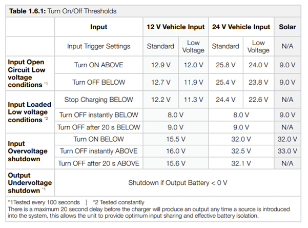
What are the turn on/off thresholds of the BCDC?
How to determine the cause of not charging from the vehicle?
Below is a list of the common causes and repairs.
Important
In this article we explain the need for testing to determine the cause of the issue. Testing may involve changes to the installation or wiring. For your safety and accuracy, REDARC recommends engaging a REDNetwork member or a suitably qualified auto electrician - Find Your Local Installer
A) FAULTY FUSE PROTECTION
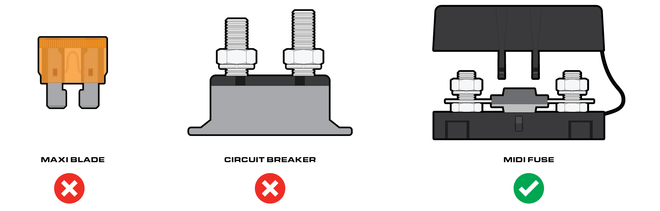
As the BCDC draws a continuous high amount of power (current), good fuse protection is critical. Unsuitable fuse protection can function correctly initially; however, it may fail over time. Blade fuses and circuit breakers are the most common cause of issues resulting in either poor performance or intermittent operation.
What to check first:
- Locate and identify the fuse protection used between starting battery and BCDC
- Locate and identify the fuse protection used between the BCDC and the Auxiliary battery.
- Visual/physical checks:
Circuit breaker: Check to see if the circuit braker is hotter than other components in the same area, this represents a bad internal connection causing the issue.
Blade fuse: Remove fuse from the holder and check both the fuse and holder for signs of heat and/or bad connection.
Note: REDARC recommends using MIDI fuses.
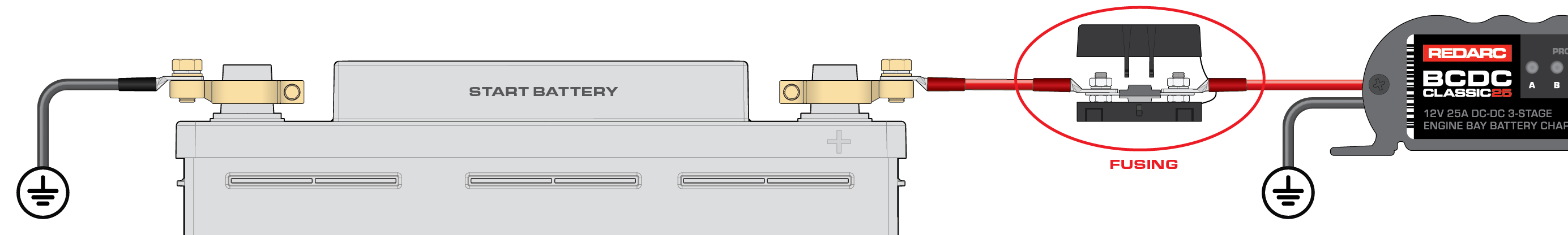
B) LOOSE CONNECTION AT THE START BATTERY TERMINAL/FUSE HOLDER OR LOOSE GROUND CONNECTION AT THE BCDC
- Ensure connection points are clean, not damaged or loose.
- Remove battery terminals and ensure a clean surface area is provided for the terminal.
- Inspect the ground wire (-) to ensure it has a suitable ground connection, such as a terminal attached to bare metal (unpainted surface)
- Ensure each crimp connection is strong, a small tug on each wire can confirm this
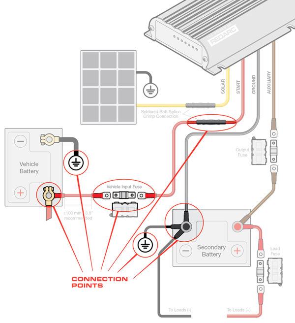
The below image shows a typical BCDC install. This diagram shows the typical connection points for an installation.